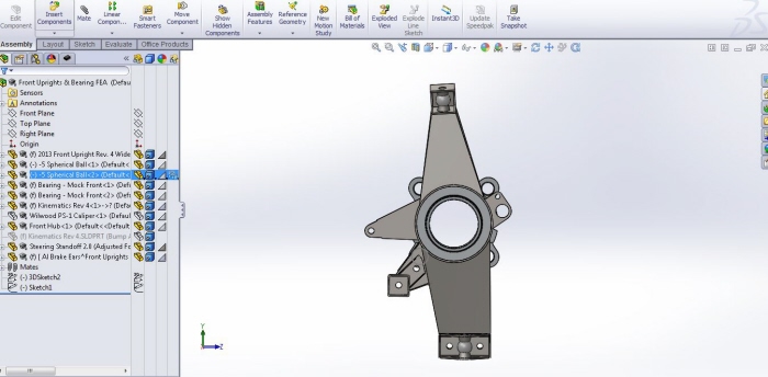
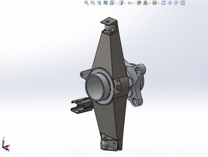
Front spindle assembly, modeled in Solidworks 2013.
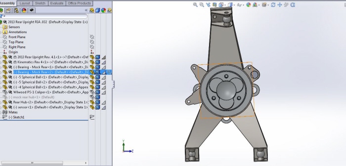
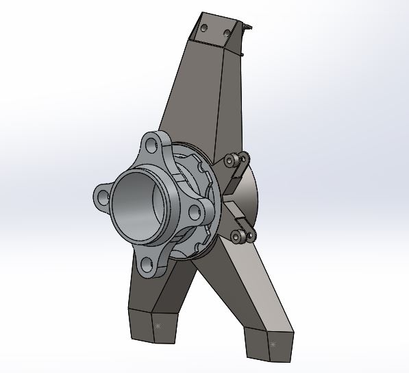
Rear spindle assembly,
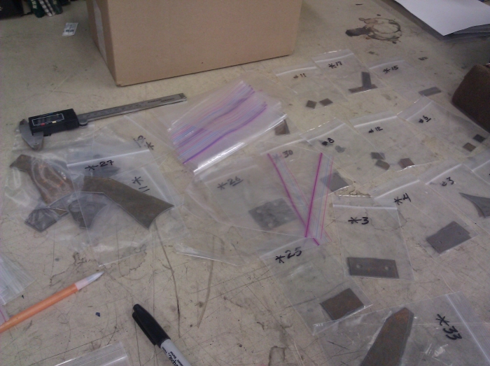
The spindle model was deconstructed into flat, interlocking pieces in the Solidworks. Drawings and material were then sent to a waterjet cutting facility.
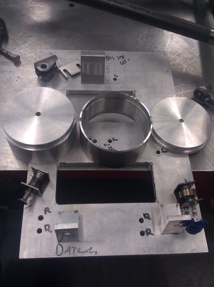
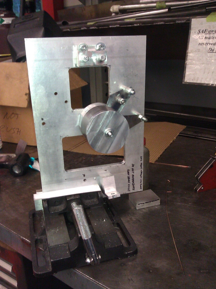
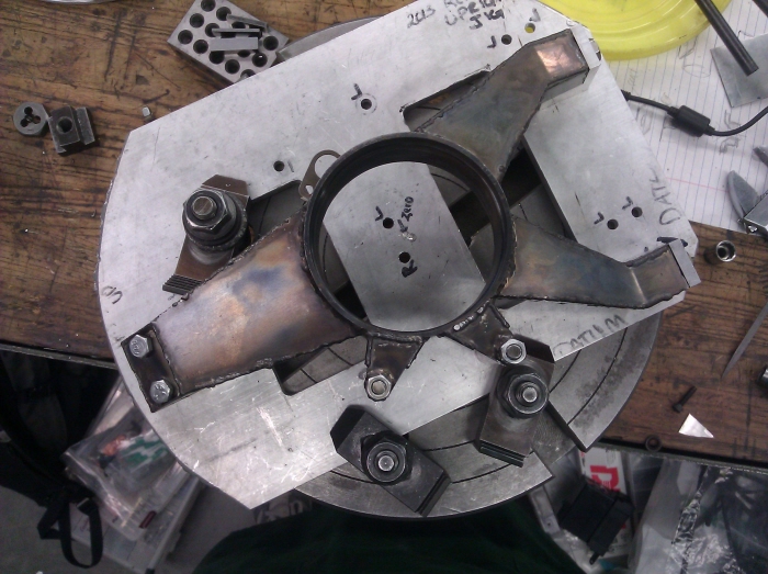
Here is the custom aluminum jig used to constrain the bearing holder while it is welded.
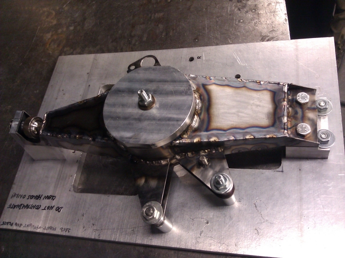
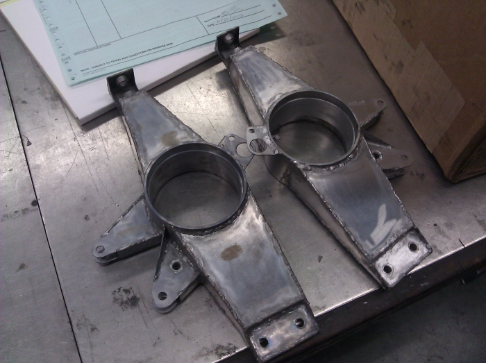
Completed front spindle.
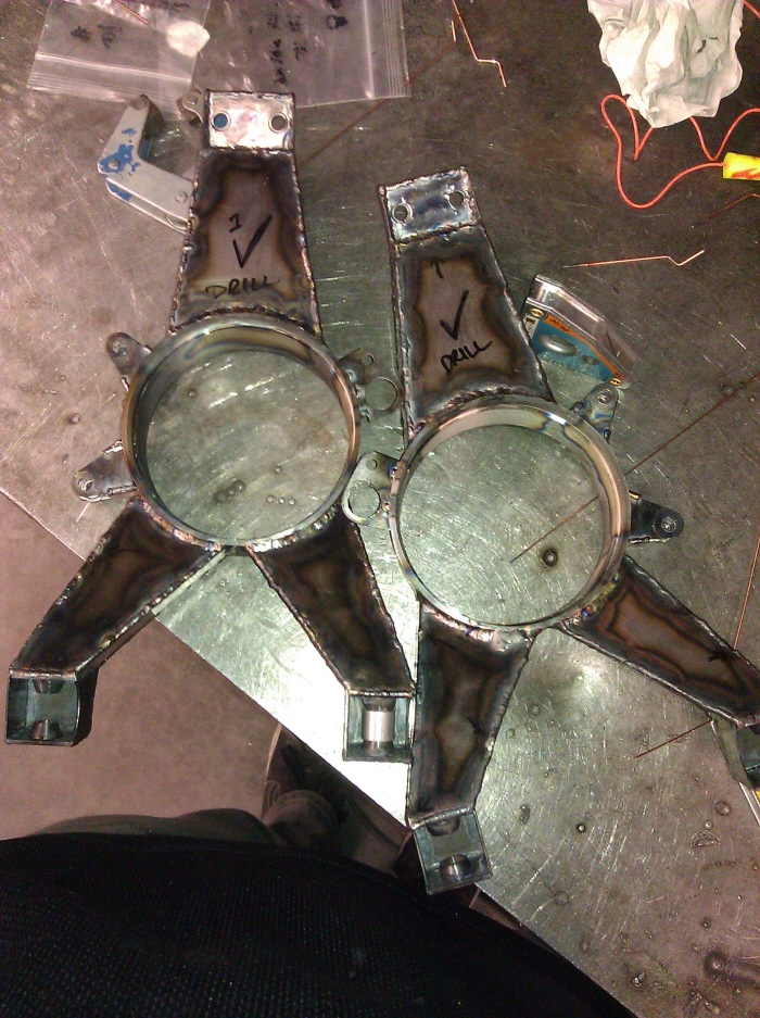
Completed rear spindles.
Post normalizing heat treatment.
Due to warping from heat treatment, the upright is mounted onto a lathe for post-machining of the bearing surface.
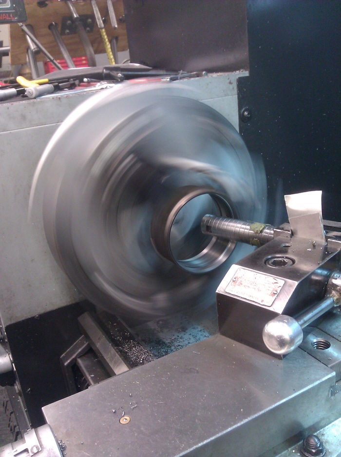
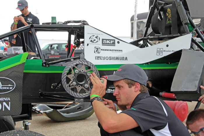
Post-machining of bearing surface.
Completed and installed spindles while the vehicle undergoes a torsional rigidity test on a custom built rig.
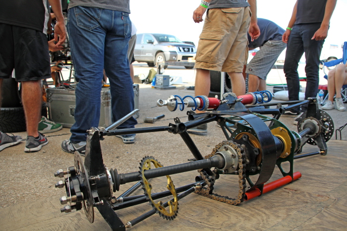
FSAE-Lincoln: With major engine issues, the rear subframe is removed for quick replacement of the motor. The spindle assembly is seen here in full.
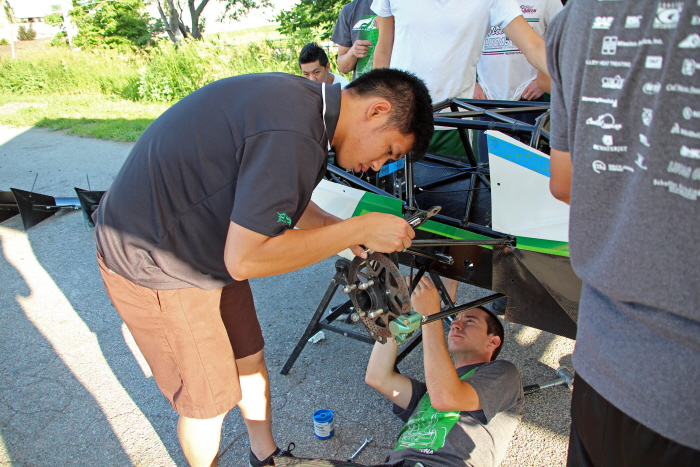
Due to vibration on the vehicle, every fastener is positively locked with locknuts, or safety-wire. Here, I am using the latter.
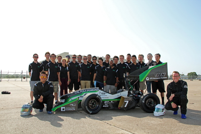
6th place overall, Lincoln Nebraska.
gLike
FSAE 2013: Outboards/Spindle Design Captain
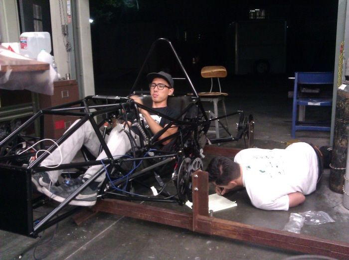
For FSAE 2013, I was responsible for the design and manufacture of the vehicle spindles. A trade study was first conducted to decide on spindle material and manufacturing processes. Theoretical loading cases were calculated from accelerometer data and input into Solidworks FEA. The steel spindles consist of 4130 steel, welded together using a custom-made jig. Parts were then normalized and post-machined.