Step 1: Toothbrush arrives via conveyor
Step 2: Toothbrush enters dispensing area
Step 3: IR Sensor detect first interruption of the beam from the toothbrush bristles.
Step 4: IR sensor “deactivated” as end of the bristle area passes through the beam.
Step 5: The toothpaste is dispensed onto the toothbrush.
Step 6: The Nozzle translates a predetermined length from one edge of the toothbrush to the other.
Step 7: The wire cutter translates, perpendicularly to the flow of toothpaste, a predetermined length to cut the flow of toothpaste from the dispenser nozzle.
Step 8: The clamps are released
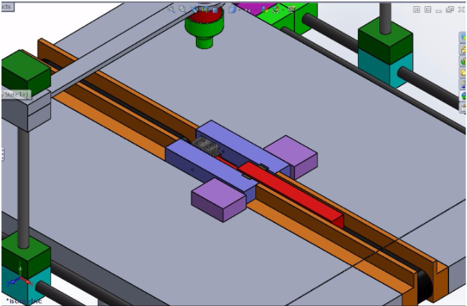
Step 9: Conveyor 1 is activated again. Conveyor 2 is activated for the first time. The toothbrush is moved along from conveyor one, across the whole dispensing area to conveyor 2.
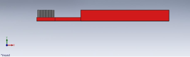
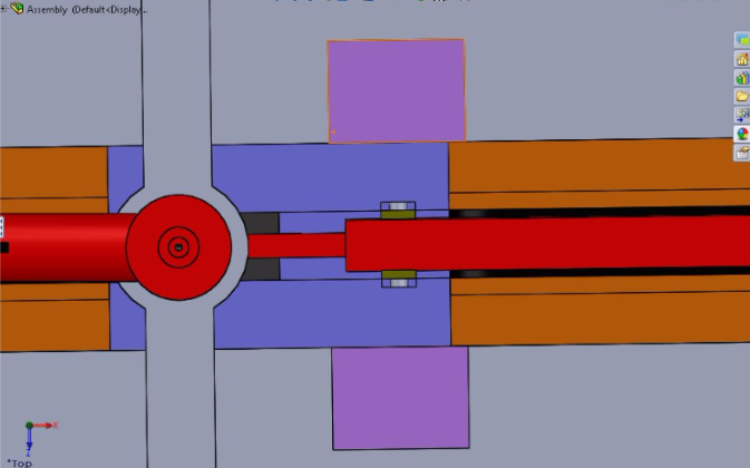
To design the toothbrush, I categorized three major areas and modeled them as rectangles:
the bristle area, the handle area, and the area in between which I called “neck”. This simplified shape plays a very important role in the technique I used to grip and fix the toothbrush under the toothpaste dispenser.
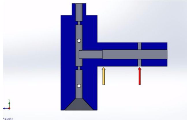
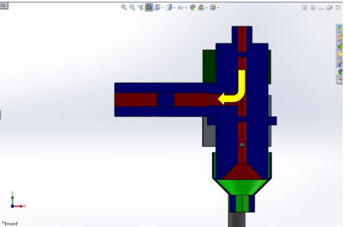
I designed my piston valve to allow me to pump toothpaste from a canister into the nozzle head. I had to ensure that the piston is able to travel a distance that is equal to the volume of toothpaste desired for dispensing by constraining it from both sides. In the figure above, the yellow arrow points to an area in the piston tunnel where the cross section decreased. The red arrow points to a hole in which I can pass a small screw to maintain the piston in the area between the red and yellow arrow.
The design of the dispenser was dependent on:
- Volume and shape of dispensed fluid (toothpaste) on toothbrush: based on empirical experiments, I approximated the shape to be a rectangular prism of 0.8 cm x 0.8 cm x 2 cm, resulting in a total volume of 1.28 cm^3 .
- Shape of the Nozzle dispensing the toothpaste: this itself was dependent on the tolerance requirement. The smaller the shape of the nozzle, the higher the tolerance. the time required to dispense a constant amount given a constant speed, and the number of iterations needed to fill the whole brush head with toothpaste. After a number of iterations I decided on a middle ground solution where my nozzle head would be a square of 0.8 cm by 0.8 cm.
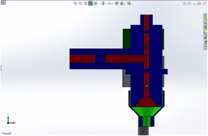
The check valve design of this system is similar to that of the piston. The valves consist of a ball constrained by a change in cross sectional diameter from one side and by a screw from the other side. There are two valves, one above the level of the piston (above the top most hole) and one under the level of the piston (above the bottom most hole).
When vacuum is created the fluid flow will be as displayed in the above picture.
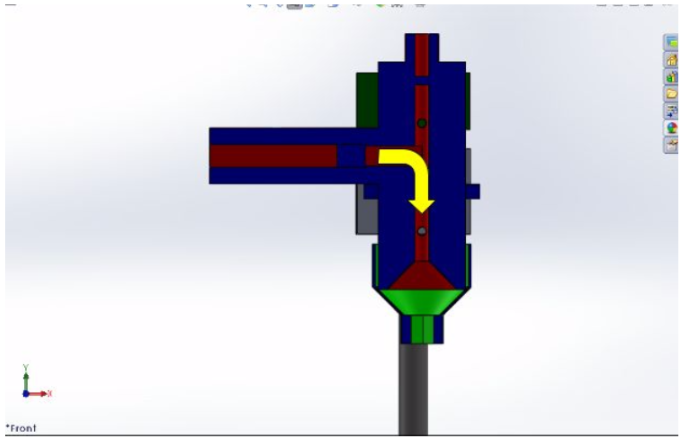
When pressure is exerted, the fluid will move in the direction displayed above.
Extra Shot
Extra Shot
If the mass of toothpaste dispensed measured was within 0.1 g of the expected
value the toothbrush continues along conveyor 2 to other processes along the
manufacturing line.
If the value is not within 0.1 g, conveyor 2 is translated along the vertical direction to a second level where units that didn’t pass the mass inspection will move to be recycled via another automated or manual process.
gLike
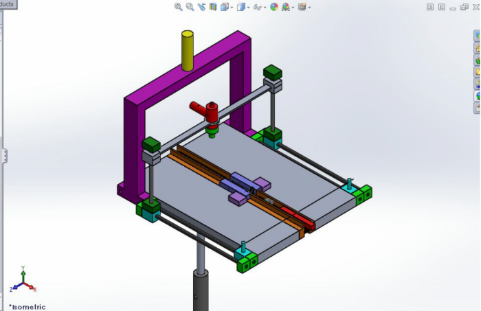
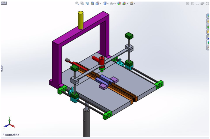
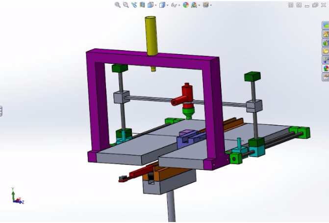
Design Challenge: Design of a Production Line Automatic Toothpaste Dispenser
The purpose of this project is to showcase the design of an automatic toothpaste dispenser, to be deployed in a factory setting.
The goals were the following:
- the setup will dispense a consistent volume every time within an accuracy of 0.1 g
- the setup will not allow for toothpaste to drip on the side of the toothbrush
- the setup will allow for at least 50 consecutive units without the need for refilling or stopping
- the setup’s maximum footprint is 0.5mx0.5m
- the cycle time for a single unit is 22 second