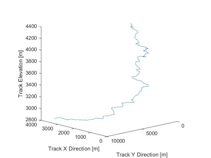
GPS data of the Pikes Peak course was used to estimate the heating conditions of the battery during the race. The graph above shows the raw position coordinates of the track.
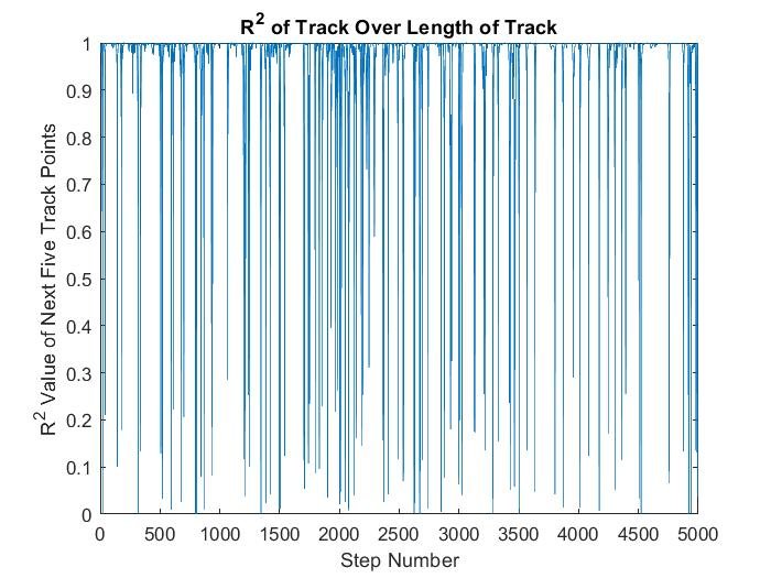
In order to estimate the throttle percentage of the motorcycle moving up the track, a linear fit was taken in 100 foot increments of track segment. The R Squared value of the fit for each segment was taken, and was used to determine the severity of the corner.
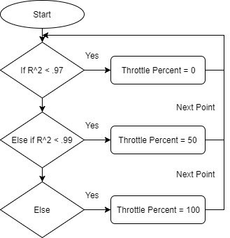
This flow chart details how the R Squared value was used to determine the throttle position. Selection of thresholds was done by watching videos of motorcycles on the course, and observing that most corners were completed at around half throttle.
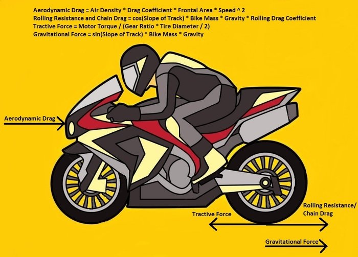
This free body diagram was used to simulate the forces on and motion of the motorcycle moving along the PPIHC course.
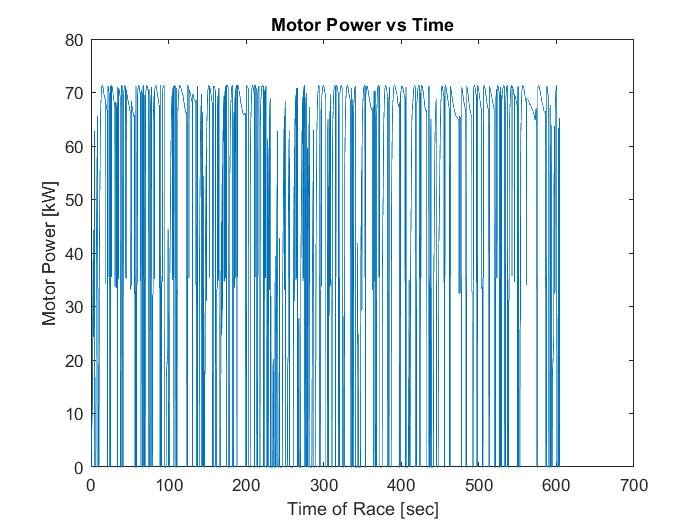
The drag coefficient parameters of the model were tuned in order to generate a peak power in the range of what was accomplished by similar electric motorcycles on the same course. In this case, around 70 kW.
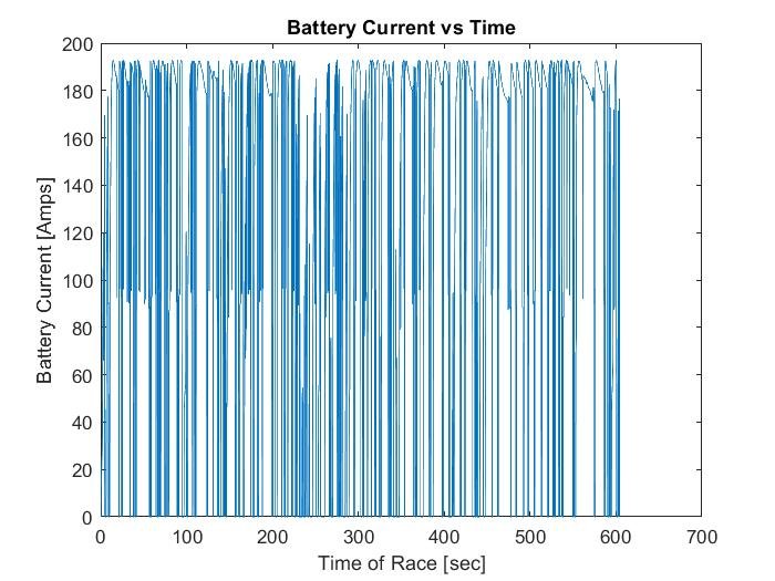
The current load on the battery was then estimated rudimentarily by dividing the motor's power output by the nominal voltage of the battery pack. In reality, the current will actually be slightly lower at the beginning of the discharge, and slightly higher at the end of the discharge thanks to the sag in voltage of the battery during its discharge.
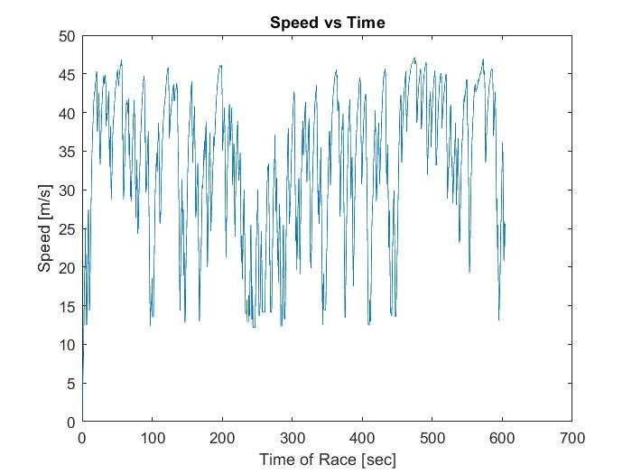
This graph shows the estimated speed of the motorcycle over the course of the race. From this data, the total time taken to complete the course is slightly above 10 minutes. This time is similar to other fast motorcycles.
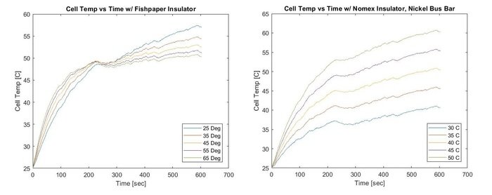
The battery current was input into the Simscape thermal model for both the ribbon and cooling plate solution concepts. The graph on the left above shows the cooling potential of the ribbon concept at multiple angles of contact with the cell, at a temperature of 45 C. The graph on the right above shows the cooling potential of the cooling plate solution at multiple different coolant temperatures. The results for both methods looked similar at 45C, so the team elected to move forward with a cooling plate solution since it offered less manufacturing challenges than the ribbon approach.
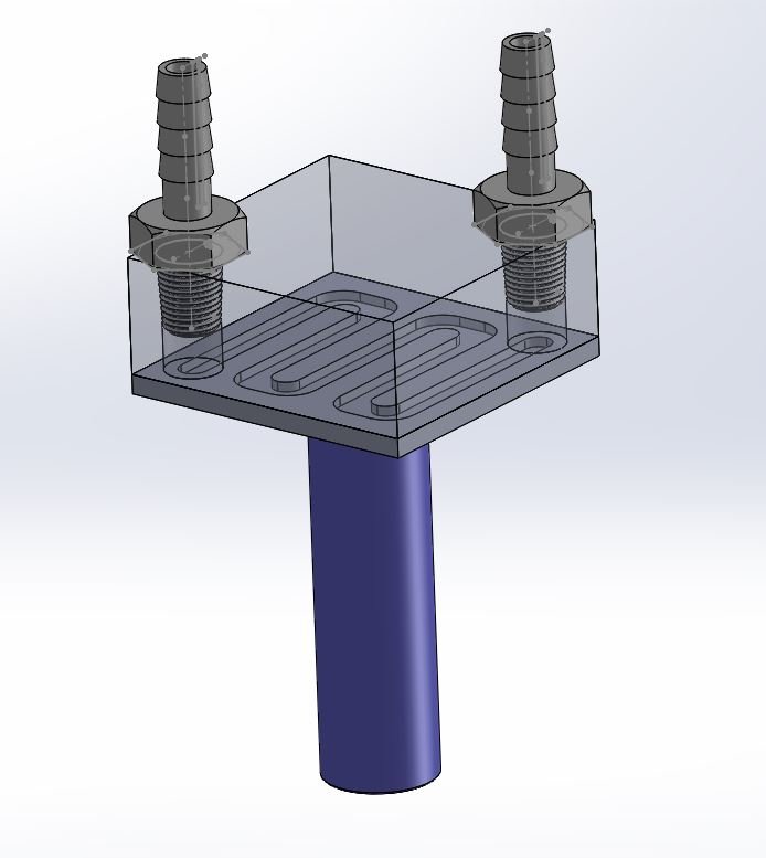
In order to validate assumptions made about the cell and its heat path in the thermal model, a single cell test setup was designed.
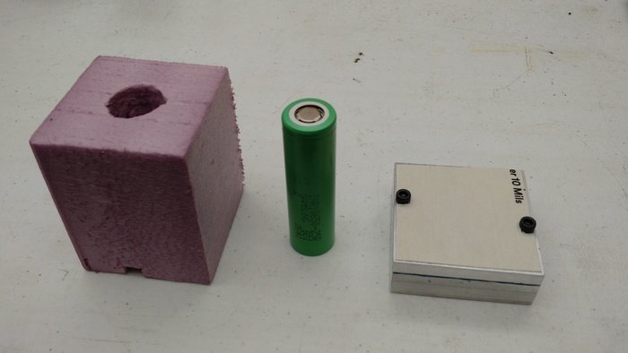
The cell would be cooled through one end at a time via an aluminum cooling plate. Convective heat transfer was eliminated by wrapping the cell body in foam insulation, to replicate the adiabatic conditions of the model outside of the cooling interface. The terminal of the cell was isolated from the aluminum cooling plate by TuffQUIN insulating paper.
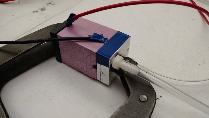
Nickel bus bars were spot welded onto either end of the cell, and the entire assembly was clamped together for testing.
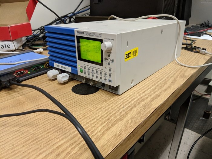
A PLZ164Wa electronic load was used to consistently discharge the cell at 10 amps for 12 minutes. This represents an 80% discharge of the cell, similar to the expected discharge of the entire pack during the race.
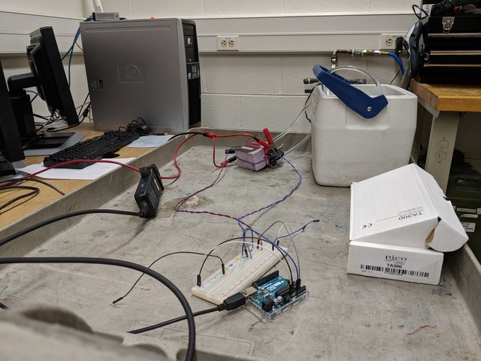
Thermistors were epoxied to the cell under test, and wired into voltage dividers on a breadboard. An arduino was used to measure the voltages throughout the test, and this data could be converted to resistances, and then to temperatures through the thermistors' data sheet.
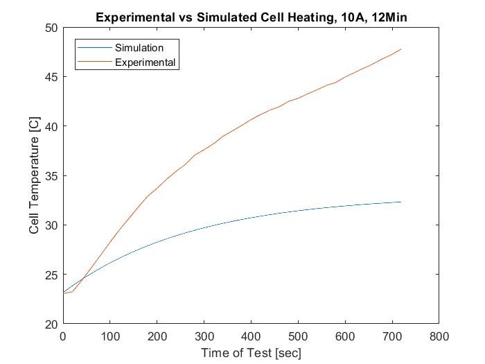
The Simscape model was found to not compare well to experimental results. The temperatures predicted by the model were significantly lower than the temperatures measured during the test.
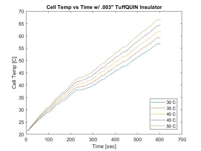
The Simscape model was 'calibrated' to match the experimental data by adding in a contact resistance node to the thermal path, and iterating it until the temperature profiles matched. The model was then run again under the conditions of the PPIHC simulation, and the temperatures were far less promising. Only under very low coolant temperatures was it possible to maintain the cell temperature below our goal - 50 C.
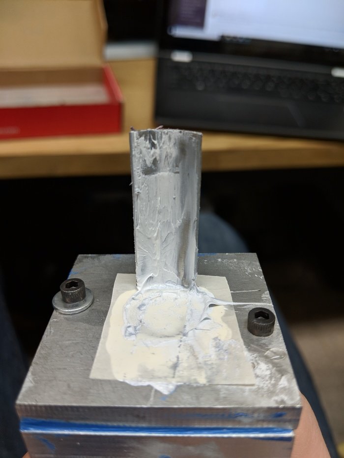
After testing the original setup with some different insulation materials and thermal pastes to verify that a cooling plate alone could not satisfy our temperature requirements, modifications to the original design were proposed in order to increase the cooling potental. The first of these was a fin that came down from the cooling plate to contact the side of the cell.
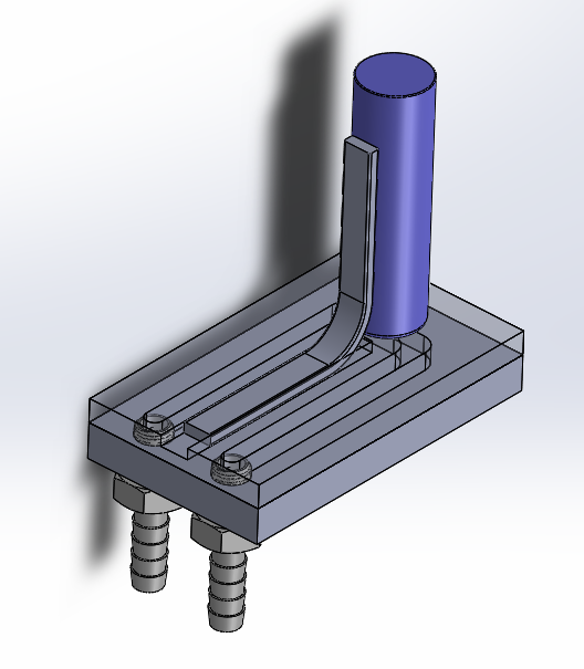
The second proposed modification was the addition of a heat pipe that would come down from the cooling plate and supplement the cooling of the cell through the cell's side wall.
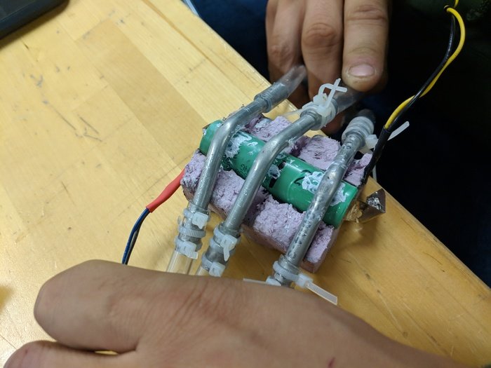
In the case that neither of the proposed modifications to the cooling plate solution were effective, the team also explored potential ways to manufacture and test the ribbon cooling concept. The above picture shows a test setup with three aluminum tubes in place of a ribbon.
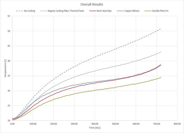
The results of this testing showed that both the fin method was the most promising in terms of limiting the heat of the cells. The ribbon and heat pipe methods also offered marked improvements over the cooling plate only method. The team is currently in the process of designing and building 9-cell prototype packs of all three of these cooling methods for further testing and evaluation.
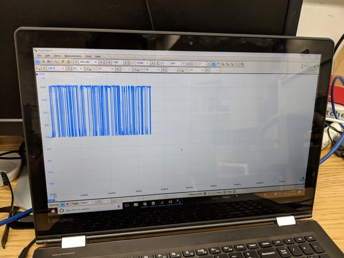
This picture is of an oscilloscope reading the current drawn from a test cell by the PLZ164Wa electronic load when the current is controlled by an Arduino. The purpose of this test was to verify that the electronic load could successfully replicate the estimated current draw conditions of the PPIHC.
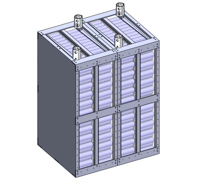
This picture is an approximation of the overall pack structure when complete.
gLike


