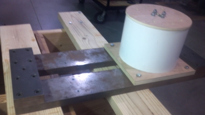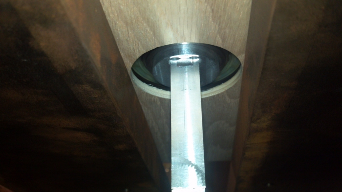
This is an image of the spar holding device prior to testing.

This image shows the lower plywood plate, a bearing, an aluminum collar, the spar, and the steel substructure. Everything besides the steel mount, bearing, and spar were cut on a 3 axis CNC machine. The only unique part of this is that I wrote all the g-code programs by hand. This requires a lot of discipline and attention to detail. Without both, programming errors could be as mundane as out of spec parts. However, they could also result in bad crashes. Discipline is required because not everyone who uses a CAM package knows how to read the posted code. It takes a while to become comfortable with all of the different commands and program structure. I program parts manually so that I do know what is going on when is start using a CAM package. A great attention to detail is required to program like this. It takes a lot of effort to ensure the tool is going to the proper locations, in the correct order, as well as avoiding any fixtures.

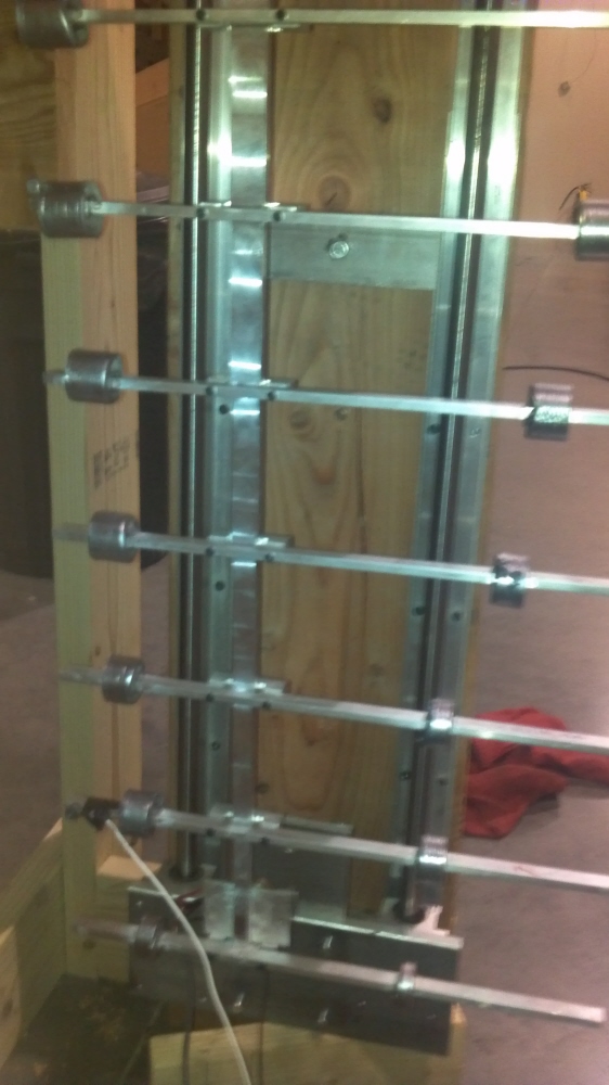
This image shows parts that I designed. Dr. Jerry Vogel helped me manufacture the bars because there aren't enough hours in a day. I cast all 16 lead masses and positioned them. The mass and location is crucial to get the desired rotational inertia and bending characteristics. A uni-axial accelerometer can be seen on the left with a white wire hanging from it. Also, the back side of the oscillator can be seen. It is the aluminum square right above the bottom most horizontal bar. The oscillator and accelerometer were driven and captured by a spectrum analyzer. The tests were performed by Dr. Christopher Whitmer.

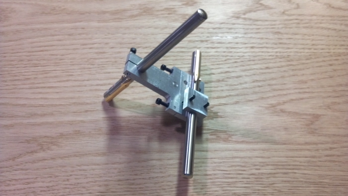
This is a mount that holds two lasers. These lasers were used to measure the rotation and bending deflection of the spar in the previous projects. It was cut on the mill in the cover image, and programmed by hand. The majority of the operations were with an 1/4 inch 4 flute end mill. It is not a complicated part by any means, but it was fun to quickly model and make in an afternoon.
gLike


