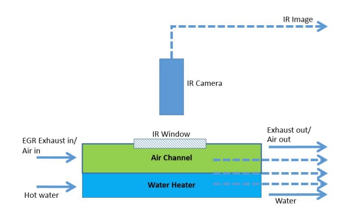
The test setup is arranged as shown in the diagram above. The infrared (IR) camera is put on top of the specimen. The specimen is generated in the tube channel (green). The water channel (blue) acts as the separator between the specimen channel and the atmosphere. It prevents the heat transfer fluctuation from the gas channel to the atmosphere causing an isothermal condition for the specimen channel (green). A window is placed on top of the specimen channel to provide access for the infrared and optical measurement.
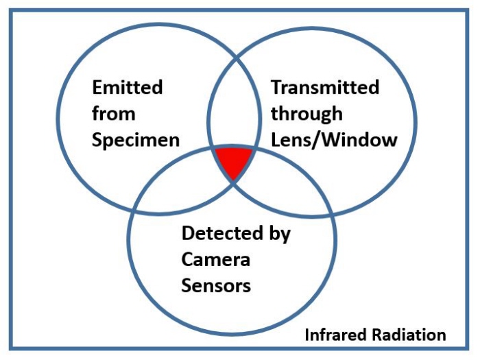
The infrared camera can only read the infrared radiation in a small range of wave spectrum. Based on the radiation of the specimen we want to investigate, the lens and test set up and the infrared camera sensors were carefully selected as shown in the set diagram above.
The infrared spectrum can be divided into three parts: one emitted from the body, reflected from surrounding, and transmitted through the medium (air, window, and lens). The measurement calibration is also needed so that the only data recorded is from the radiation emitted from the source through test set up window and lens.
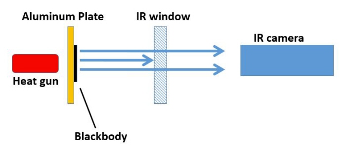
A simple scenario was set up to calibrate the camera setup input values on the camera user interface. The heat gun was placed behind an aluminum plate with a black body on it, and the other test experiment with investigating specimen on it. The only radiation expected in this scenario is emitted directly from the black body or investigating specimen.
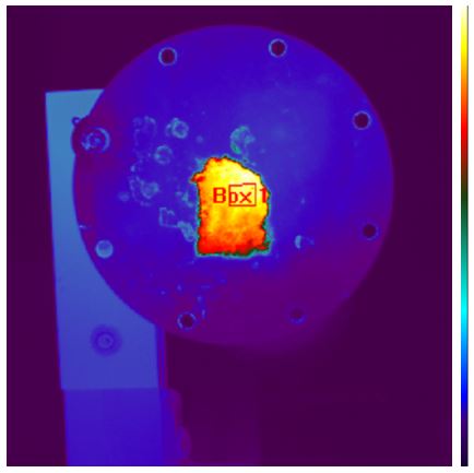
This is a result from a simple heat source scenario for infrared camera calibration.
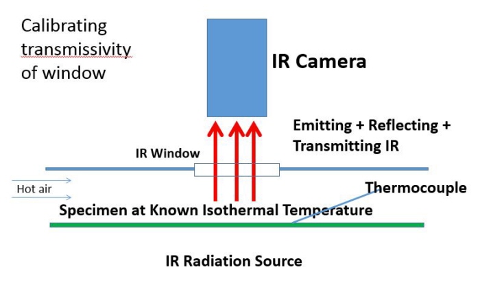
The transmissivity calibration is done by an isothermal test. In this test, the heat is applied to the channel and is convected to the black body specimen. The infrared camera read the radiation emitted from the specimen and transmitted through the window and air in the channel.
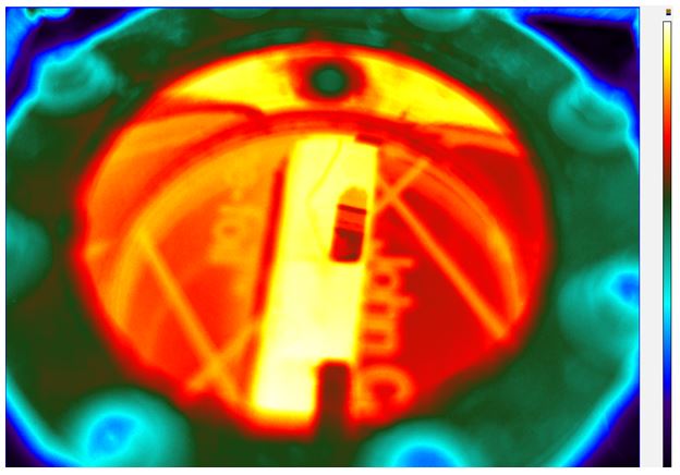
This is a snapshot of the result from the isothermal test. The channel is glowing in orange-yellow color, while the specimen glows a little bit brighter in the channel.
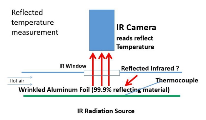
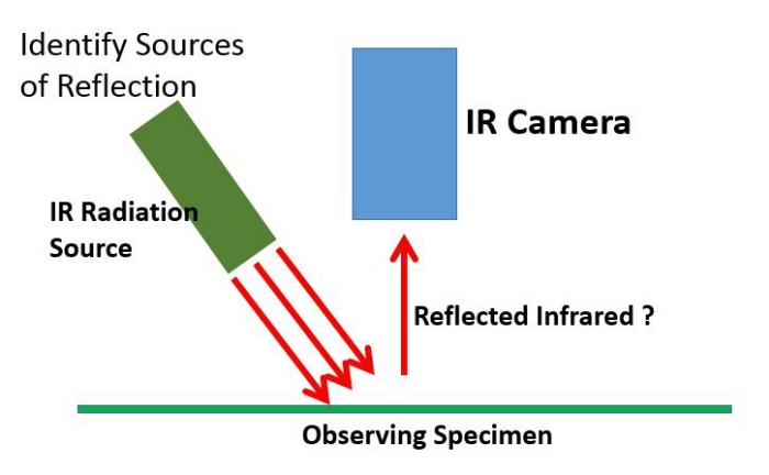
A reflectivity test is done to understand the effect of the radiation reflection from the specimen surrounding on the value measured in the IR camera. The test setup is similar to that of the isothermal test. The only different is the black body specimen is replaced by the 99% IR reflecting material. The reading on the reflecting body determine the amount of infrared reflection on the infrared camera reading.
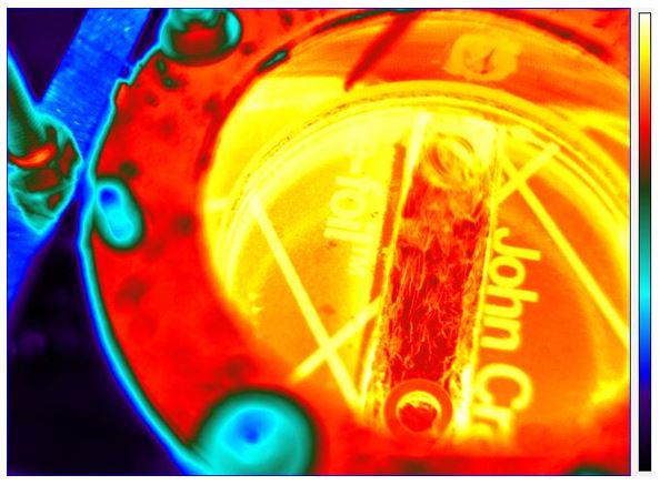
This is a snapshot of the result from the reflectivity test. The channel is glowing in dark orange-red color.
The second reflection test was done to calibrate the emissivity value of the specimen. In this test, the window is eliminated and a heat gun is pointed at the specimen. The infrared camera read the radiation value from the specimen. The reading was then verified with the thermostat reading to calibrate the emissivity value of the specimen.
A summary of the undisclosed part of my summer internship work is included in this file.
View PDF
View PDF
gLike
Exhaust Gas Recirculation (EGR) Cooler Fouling Research
This project focuses on the research on the testing method to visualize and measure the properties of the deposited particulates in a simulated testing exhaust gas recirculation system of a diesel engine. The research findings are published in the SAE International paper: http://papers.sae.org/2013-01-1289/
My tasks, as a research assistant summer intern, on this project were to set up testing equipment, record data, to analyze possible testing using CFD, and to design alternative testing equipment using CAD. A summary of my summer work can be found in the Project Asset PDF file attached.