7-DOF suspension model.
System of equations to be solved.
Variable names, symbols, and values used.
Figure 2: Core System
Figure 3: Ground Input Signal and Subsystem. Front left tire experiences 2cm step over 1s. Other tires remain flat.
Figure 4: Rubber Term Subsystem. This subsystem computes the value of the term caused by the stiffness of the rubber in the tire.
Figure 5: Spring Terms Subsystem
Figure 6: Spring Term Sub-Subsystem – Front Left
Figure 7: Damping Term Subsystem
Figure 8: Damper Term Sub-Subsystem – Front Left
Figure 9: Front Left Unsprung Mass State Equation Subsystem
Figure 10: Front Right Unsprung Mass State Equation Subsystem
Figure 11: Rear Left Unsprung Mass State Equation Subsystem
Figure 12: Rear Right Unsprung Mass State Equation Subsystem
Figure 13: Bounce State Equation Subsystem
Figure 14: Pitch State Equation Subsystem
Figure 15: Roll State Equation Subsystem
Figure 16: Unsprung Mass Displacements
Figure 17: Sprung Mass Bounce
Figure 18: Sprung Mass Pitch
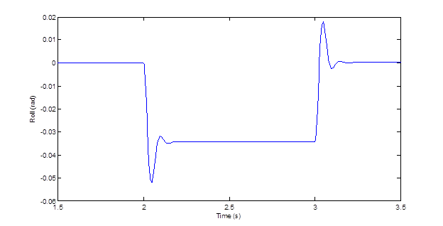
Figure 19: Sprung Mass Roll
gLike
Vehicle Suspension Model

With a team of 2 mechanical engineers, we developed an analytical simulation of a 7-DOF vehicle suspension system evaluating the bounce (body and individual tire), pitch, and roll of the vehicle in response to elevation changes in the road surface. My contribution to this project was researching the mathematical relations of each degree of freedom and implementing the equations into an iterative solution finder (Simulink).

Noah Barker-Eldon
Mechanical Engineer Perkasie, PA