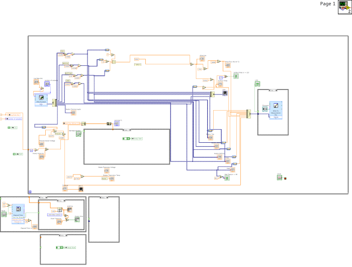
Block diagram of the LABView vi that processed data from the system at the time I began working on it. The three while-loops at the bottom show the alternate states of the while loops in the main body.
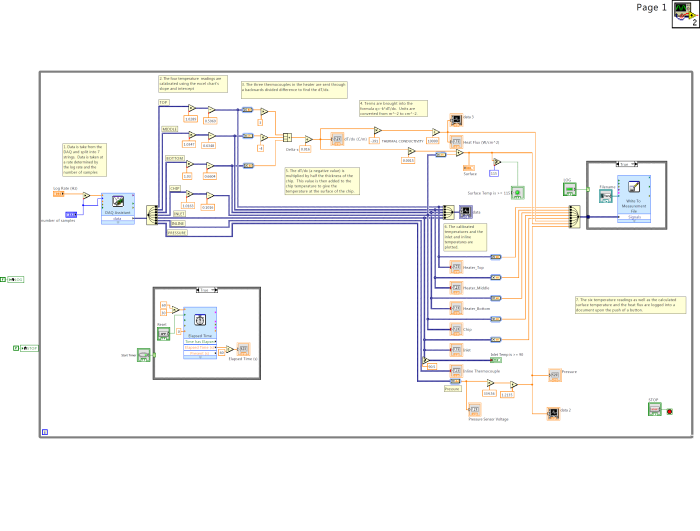
Block diagram of the LABView vi that processed data from the system after I had finished making updates to it. In addition to major changes to the code, I organized the wiring and fully commented the program's structure so that future employees would be able to make their own additions without the tedium of figuring out the structure themselves.
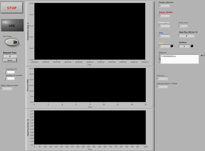
GUI of the LABView vi that the researcher monitored and collected data from. This is the finished version of the GUI after my additions and changes.
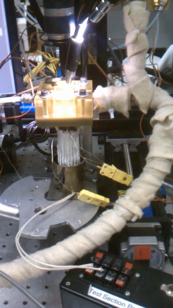
Original system while in use. High intensity lamps were necessary in order to record video from the slow-motion camera.
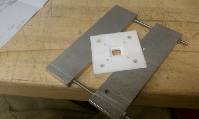
Redesigned base plate. Previous iteration used a high temperature thermoset polymer whose maximum operating temperature was below our desired value. This replacement was made out of macor ceramic whose maximum operating temperature was 4x greater. Custom clamps became necessary to prevent the plate from fracturing.
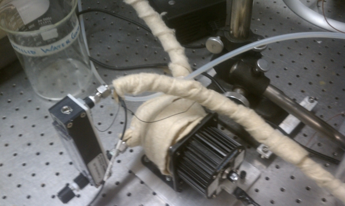
Variable speed pump and rotameter. Path from reservoir to heat exchanger was insulated wherever possible.
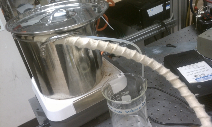
Hot water reservoir. Water was maintained at 99°C.
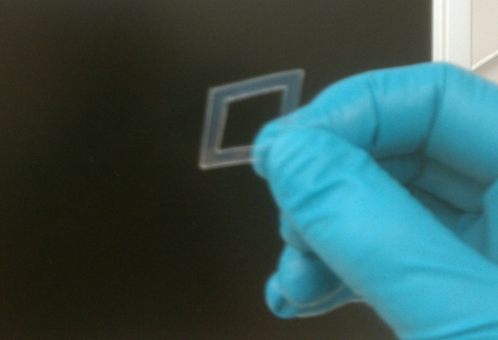
New gasket for chip-base interface.
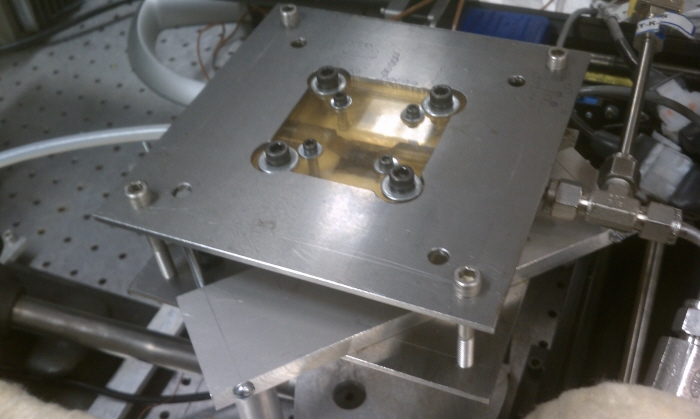
Chip, base, and manifold were sandwiched in between two plates so that the pressure would be distributed evenly along the surface of the manifold and ceramic base. These larger clamps allowed me to secure the system to a vibration isolation table by two supports while still allowing access for the heater to reach the chip.
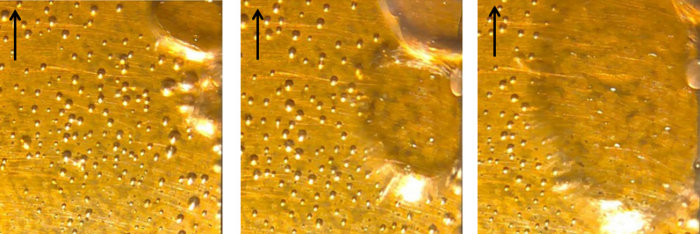
Microscopic bubble formation caused by the evaporation of super heater water passing over the chip at a high flow rate.
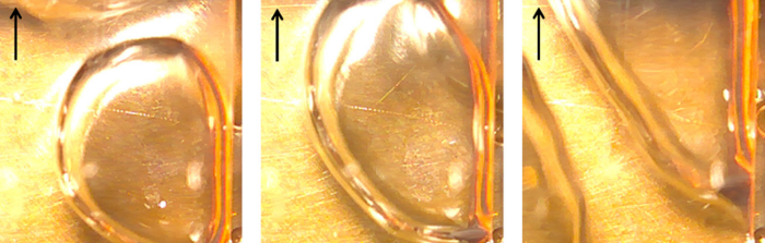
Microscopic bubble formation caused by the evaporation of super heater water passing over the chip.
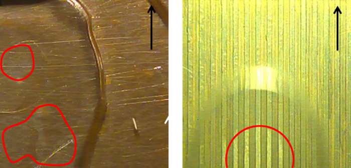
Bubble formation on a plain chip and a chip with microchannels. My main area of interest was focused on the effect of surface wettedness on the heat flow rate; would direct contact between the bubbles and the chip surface slow heat flow as heat transfer from chip-to-vapor would be less than chip-to-water?
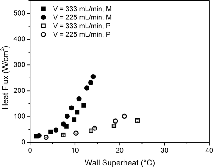
Towards the end of my stint researching flow boiling, I had reached a heat flux of 300W/cm^2.
gLike
Flow Boiling Research
In this project, I designed and ran experiments to test the rate of heat loss using flow boiling as a means of heat extraction. I redesigned the testing setup to utilize new materials and allow testing at higher temperatures and a greater heat flux. I rebuilt the control and DAQ software for better visualization of data, updating DAQ hardware, and to allow future revisions to be implemented easily.


