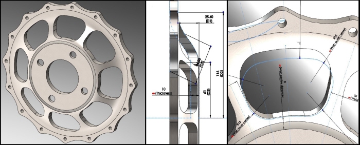
Summary of key aspects of the hubcap model.
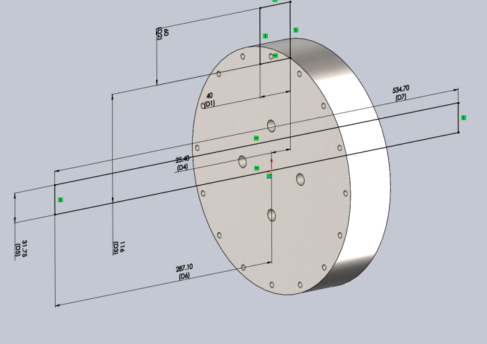
The first stage of the model - the extruded block (extruded cut bolt holes were added in a previous step not shown)
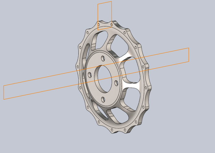
Finished hubcap which clarifies the first step - revolved cut for the central hole and revolved cut for the web
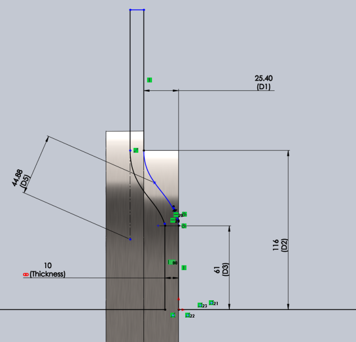
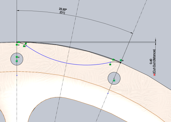
The second major step - revolved cut of the major shape of the hubcap - the named dimension 'Thickness' is the thickness of the whole hubcap, and can be varied by a FEA design study to test stress in the structure at different thicknesses.
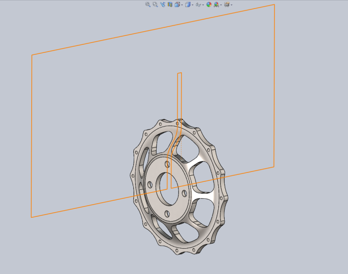
The previous revolved cut sketch overlaid on the finished hubcap model to clarify the result of the sketch.
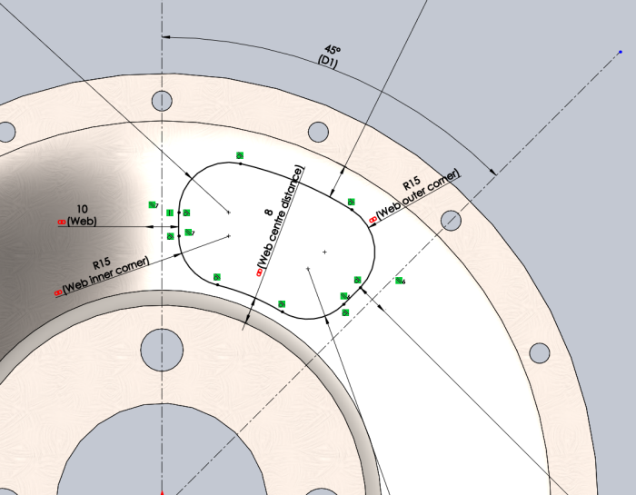
The sketch for the weight-reducing 'web' of the hubcap, with named dimensions and constraints very carefully set so that the named dimensions alone are changed to control virtually everything about the geometry of the web, for purposes of FEA optimisation.
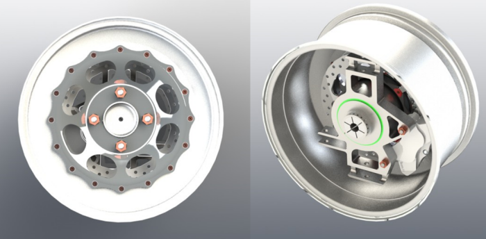
High quality renders of the full wheel assembly with hubcap attached as shown.
gLike