This is the assembly process that is particularly difficult for Datacard assemblers to perform by hand. The shaft on the left holds the top yellow piece and bottom gray piece together and also secures the spring between them. The spring is very strong and is what makes this assembly so difficult. The spring allows the top yellow piece and bottom gray piece to perform a hinge action.
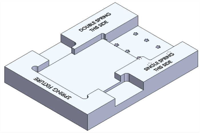
This is the final model of one of my spring fixture designs. This fixture is used to install a single spring into the previously shown assembly.
This fixture is similar to the previous one show, however this one is used on sub-assemblies that requrie two springs. The sub-assembly is situated in the lower left pocket, the springs are positioned in the grooves in the block and held in place by magnets. Then the clamp is closed, compressing the springs against the sub-assembly, and locking in place. Then the assemblers have both of their hands free to insert and secure the shaft. Finally, release the clamp and voila! The sub-assembly is complete.
The base plate model can be used for both the single and double spring installation fixtures. This reduces the number of part numbers and CNC codes that Datacard needs to maintain.
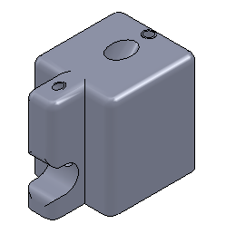
This is the single spring installation head.
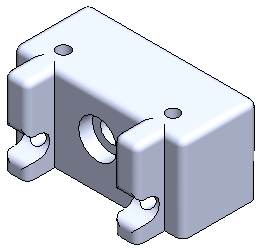
This is the double spring installation head.
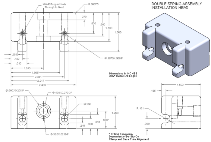
Machining drawings were used to communicate design requirements to the machining staff. I learned how to appropriately use datums for easy reference and how to manage dimensioning tolerances.
gLike
Spring Installation Fixtures - Strength

Over summer break 2013 I had the opportunity to work as a Manufacturing Engineering Intern for The Datacard Group in Minnetonka, MN. One of the responsibilities of a manufacturing engineer at Datacard is to design and fabricate fixtures to help improve the assembly process for our assemblers. I was asked to help improve the assembly of a specific module component by creating a new fixture. This involved evaluating available resources, learning about the assembly in question, creating 3D CAD models in the SolidWorks CAD package, and machining and testing new fixtures. This project taught me a lot about how to design for manufacturability, utilize available resources, and a lot about general machining practices. This project helped me develop my strengths which include CAD modeling, project planning, and research and development. It tested my patience, however, as I experienced some roadblocks along the way, mostly pertaining to documentation support and seeking higher level approval.