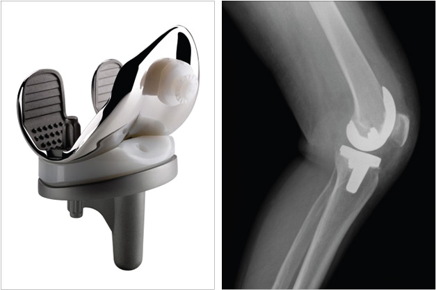
The unique geometry of the Future Knee system combines enhanced stability with natural knee kinematics. The concept is based on the medial-centred rotation and lateral patella tracking as exhibited by the normal knee.
Rotation in flexion is achieved about the prominent spherical medial condyle, which maintains high contact area and low surface stress in the poly tibial insert throughout the full range of motion.
The knee has been in clinical use since 2009.
During a total knee replacement the surface of the upper bone (femur) is replaced with a rounded metal component called the Femoral Component (1) which comes very close to matching the curve of the natural bone. The surface of the lower bone is replaced with a flat metal component called the Tibial Component (2), and a thin polyethylene part to serve as the cartilage (3). The underside of the kneecap (patella) may be replaced with a polyethylene component (4).
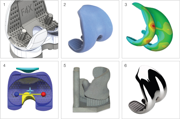
1. Implant CAD models are demanding in that they require surfaces that are organic yet predictable and highly controlled where components interact.
2. RP samples of first concepts to be evaluated by surgeons in focus groups.
3. Finite element analysis to evaluate component stress during gait cycle.
4. Using LifeMOD human simulation software to predict kinematic performance.
5. Laser sintered prototypes for mechanical testing.
6. DMLS prototype finished for marketing photography.
4 designers, 18 months, 270 product designs.
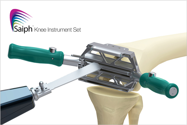
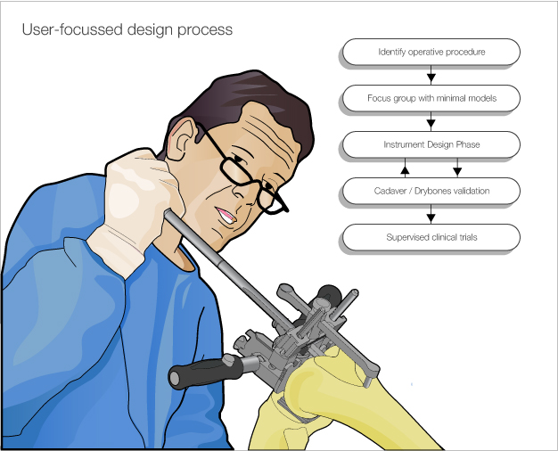
A knee replacement procedure requires an extensive kit of instruments specifically suited to the design of the implant. To meet the specific and often demanding needs of the surgeon, these instruments must be highly precise, intuitive to operate, and resistant to error.
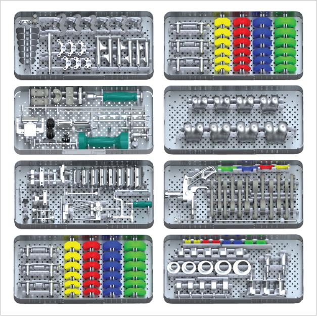
Historically, orthopaedic instruments have been a basic ‘means to an end’. Tools for measuring and cutting bone and ligaments within precise tolerances, but little regard has been given to the surgeon’s experience of the tools.
As the single Industrial Designer on the team I wanted to bring an understanding of human factors into the engineering team which would allow us to design a set of instruments that would improve the relationship between the surgical staff and the instrument set.
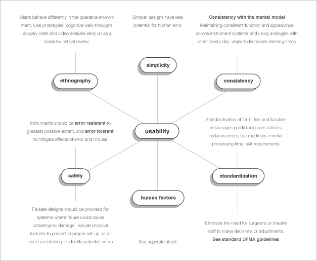
Shown here are excerpts I wrote as part of a presentation to introduce the engineering team to basic principles of user-centred design that might apply to the development of orthopaedic instruments. This presentation was initially given to the knee engineering team, then later expanded and presented to the entire design group by myself and my colleague Paul Williams.
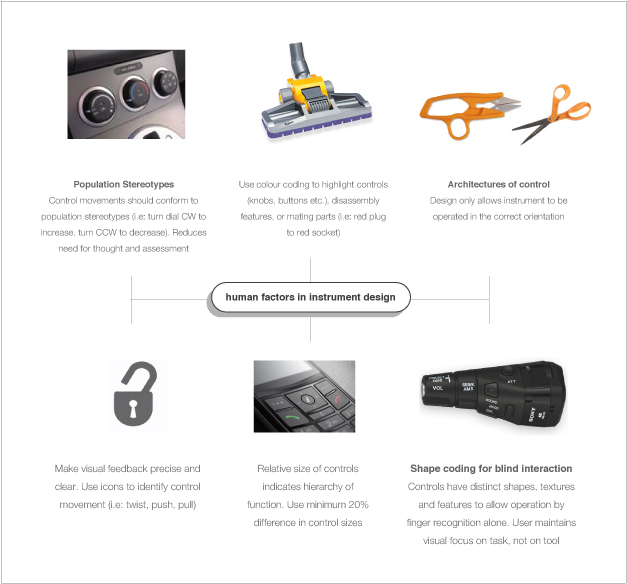
Shown here are excerpts I wrote as part of a presentation to introduce the engineering team to basic principles of user-centred design that might apply to the development of orthopaedic instruments. This presentation was initially given to the knee engineering team, then later expanded and presented to the entire design group by myself and my colleague Paul Williams.
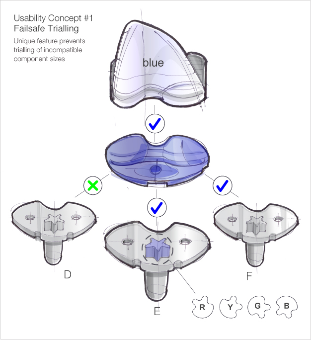
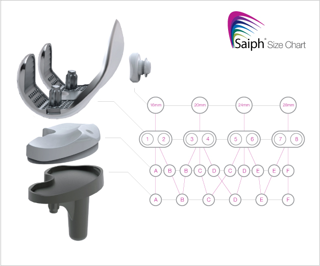
One example of how a user-focused approach has been integrated into the instrument set. This failsafe feature prevents incompatible component sizes being assembled together during the operating procedure.
Other concepts taken forward included standardised quick-connect handles, failsafe cutting blocks that prevent accidental removal of too much bone, and controls that were consistent in appearance and function across the entire instrument set.
The Future Knee project was pioneering in the use of a design 'panel' of key opinion leading surgeons.
The team was used in simulated surgery settings to observe realistic behaviour patterns. Prototypes in the focus groups reflected the stage of development of the instruments; at first just storyboards and 'sillhouette' rapid prototypes devoid of features, to encourage blue sky discussion, then becoming more defined as decisions were made by the surgeon team.
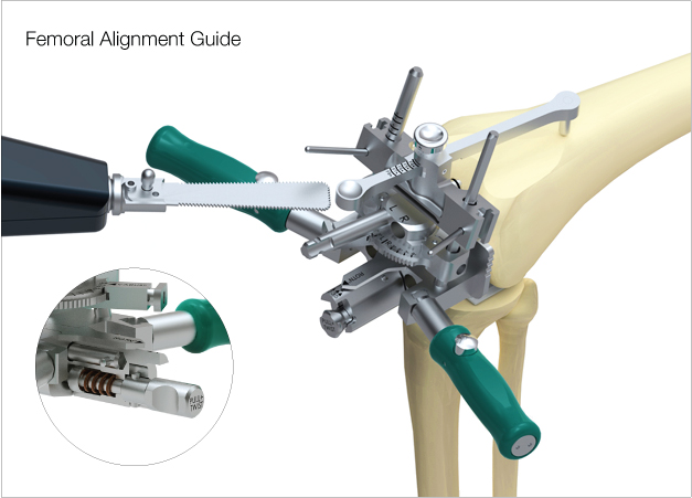
Alongside my Industrial Design input I was also responsible for the complete design engineering of over eighty of the instruments in the set. The Femoral Alignment Guide, shown here, is a key instrument in knee replacement procedures.
A unique feature of this design is the ability to make adjustments as small as one degree, by hand. This is made possible by a cam mechanism which reduces the movement at the control by a ratio of 10:1.
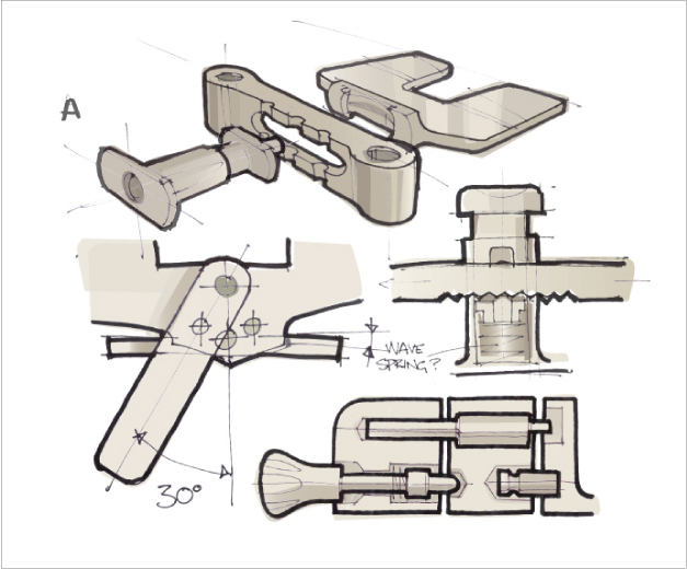
Shown here are some of my communication sketches for the offset cam mechanism.
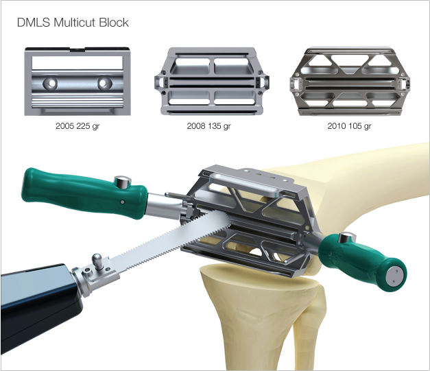
The multicut blocks are saw guides used by the surgeon to remove the surfaces of the femur before the rounded surfaces are ‘put back’ using the implant.
The cost of manufacturing these items is historically high due to the precise tolerances required for saw guidance.
Since the weight of the instruments in the tray was also a concern (there are 8 blocks per set), we saw an opportunity to use Direct Metal Laser Sintering, to create the blocks in place of conventional CNC machining.
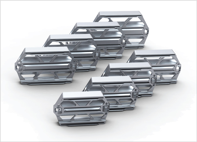
DMLS can be used to create hollow shapes which can be cheaper than machining since part cost is directly proportional to weight. There is also very little manual finishing required, provided the blocks are designed appropriately to optimise surface quality.
In tandem with a Production Engineer I worked directly with the manufacturer to design and validate the new instruments. The resulting design gave a reduced part cost and a greater than 50% weight reduction over the CNC design.
gLike
Future Knee system
Future Knee system