Shaft head was considered rigid and since each arm was identical, simulations were run on only a single arm.
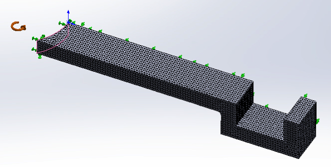
Since the arm is symmetrical along the axial direction, only half the arm was used for Stress simulations to cut down on simulation time. Symmetrical restraints were used.
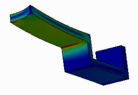
Simulations revealed the max stress occurred in the underside fillet.
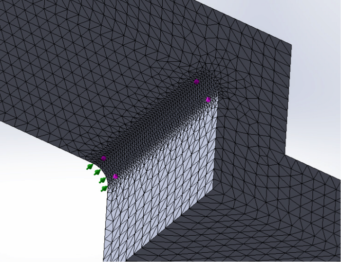
Since max stresses occurred in the underside fillet, mesh controls were used to focus on the region and keep processing times at a minimum.
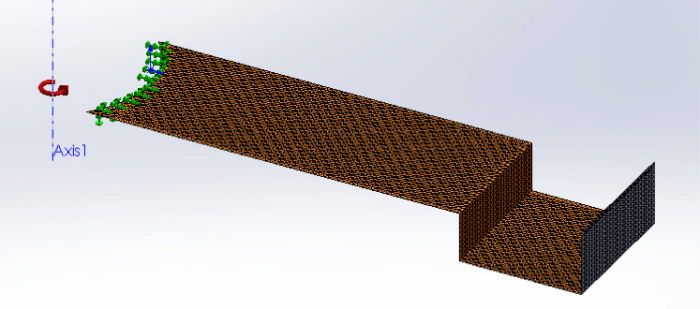
For vibration analysis, shell meshes were used since the part's thickness was much thinner than its length.
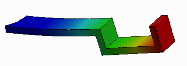
Max Axial Deflection occurs at then end of each arm.
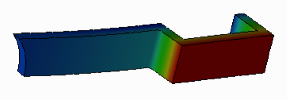
Max Radial deflection occurs on the bottom small surface of the arm.
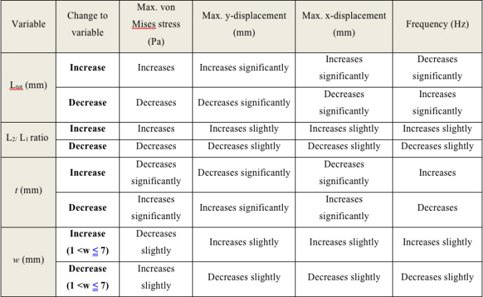
Modifying various dimensions produced noticeable effects on each requirement on of the design. This was used as a rough guide to find the optimal design.
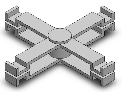
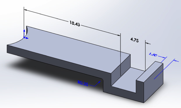
Final governor design.
gLike
FEA Governor Design Project
For this project, the optimal specifications for a centrifugal governor were found using Cosmos Finite Element analysis in SolidWorks. Certain constraints were placed on how a single arm could deform at a specified rpm. Furthermore the natural frequency at speed was limited. Each simulation was run multiple times with different mesh sizes in order to make sure results converged.