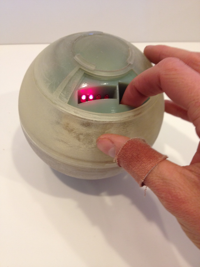
The goal of this project was to create a device that would allow someone to charge his or her cell phone when away from an outlet, using power generated by human motion.

I began by researching existing devices that generate power through human motion, both through active (intentional) and passive (non-intentional) methods. I considered thermoelectric, mechanical, and magnetic induction options for the generator, and I decided on a magnetic induction system as it had the highest power density. Using motion from a person walking to power the system, it would be able to generate power passively.
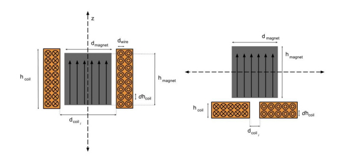
There are two ways to generate power in a coil through magnetic induction: by moving a magnet through a coil and by moving a magnet across a coil. I considered both options, as pictured here. I created a computational model in MATLAB for each case to estimate power outputs with varying parameters.
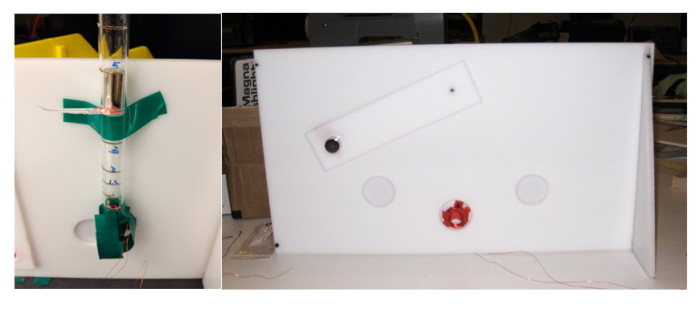
I ran simple experiments for both cases to confirm and calibrate the MATLAB models, varying the size of the magnet and coil, the distance between the two, and the speed at which they passed each other.
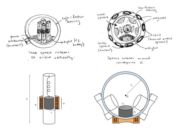
I brainstormed different configurations for the magnet-coil system and identified two promising options. One option was a tube in which a magnet is suspended on a spring and oscillates vertically through a coil in response to the motion of the user; the other was a set of two sphere, with magnets embedded in the inner sphere, which moves relative to coils on the outer sphere. I decided to move forward with the spring-column system due to greater power output and ease of construction.
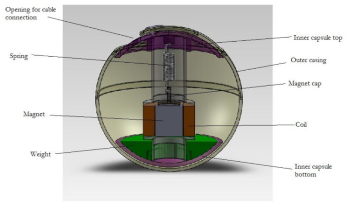
I used my computational model to generate optimized component dimensions. Above is a SolidWorks rendering of a cross-section of the prototype. The column is embedded in an outer sphere, with a weight at the bottom of the column, to enable it to re-orient vertically regardless of how it is placed into a bag.
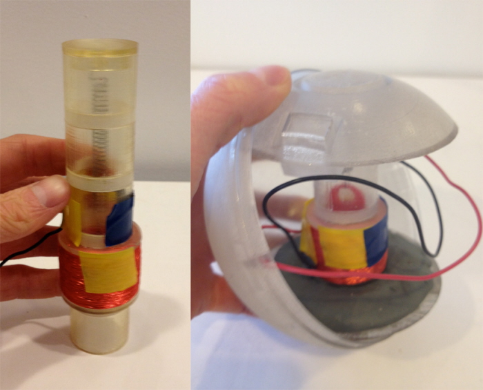
I created prototypes of the column and capsule using 3D-printed materials. I tested power generation and the ability of the inner capsule to rotate within the outer sphere.
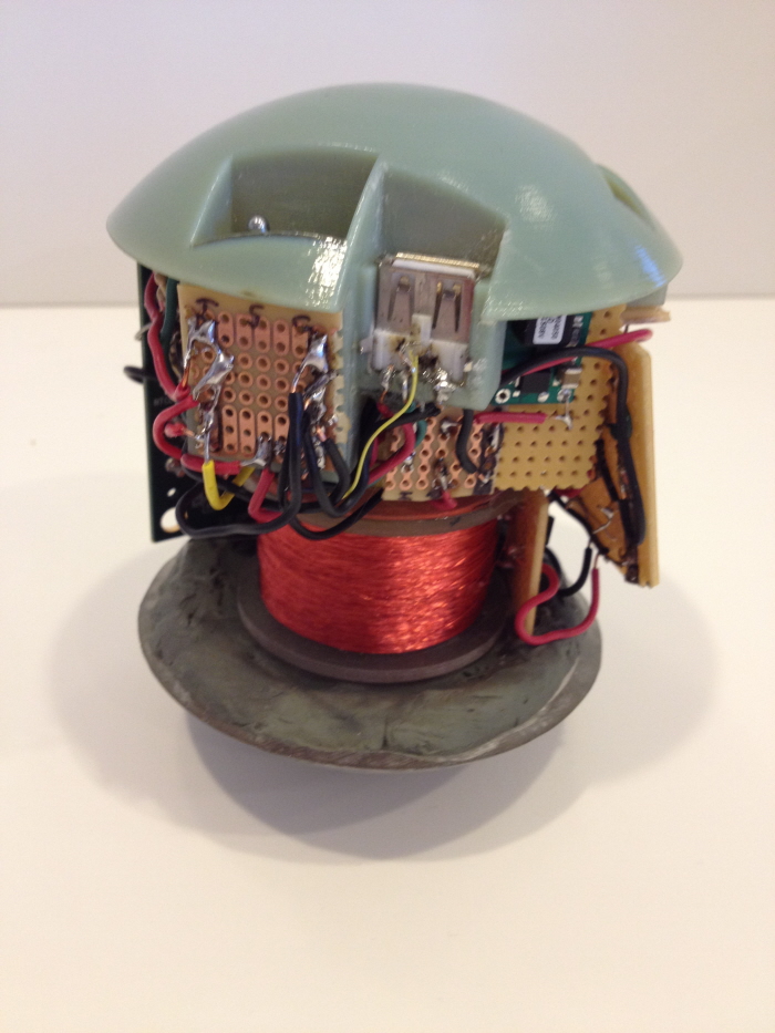
I constructed a final prototype including electronics. Output from the coil passes through a bridge rectifier, an energy harvesting module, a boost converter and a battery charging chip to a 3.7V lithium polymer battery. The battery discharges through a boost converter to a type A USB port.
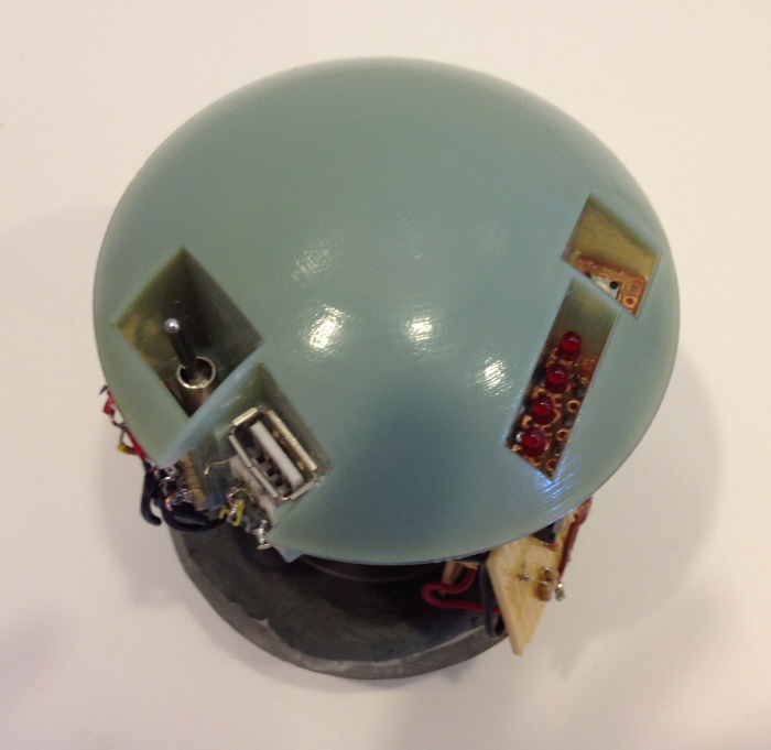
The top of the inner capsule. The user flips the switch to begin charging when a device is plugged in to the USB port. A series of LEDs displays the battery charge status when a button to the right of the LED series is pressed.
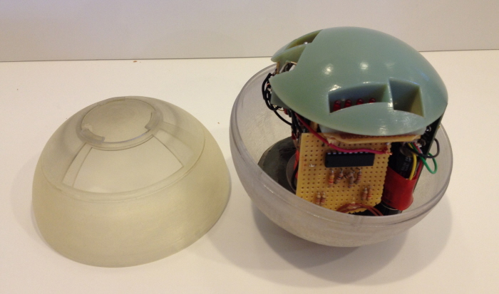
The inner capsule sitting within the outer casing. The two halves of the outer casing were detachable for prototyping purposes. A sliding panel at the top of the outer sphere allows the user to access the USB charging port/switch and the LED series when needed, otherwise keeping them covered for protection.
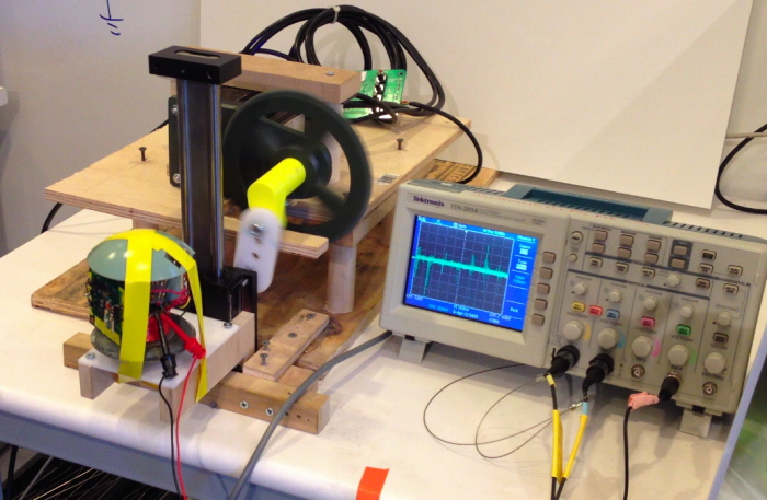
I constructed a test apparatus to measure the performance of the prototype, using a DC motor, a vertical slider, wood, acrylic, and 3D-printed parts. It simulated walking by moving along a vertical trajectory at walking speed (around 100 RPM), approximating the vertical displacement of the hips. Power input to the battery was found to be 1.5 mW, which would be improved in further iterations with greater efficiencies in electronic and mechanical components. The prototype was able to successfully charge an iPhone.
gLike