BACKGROUND
Many universities and companies are currently trying to increase the efficiency of solar photovoltaic panels by experimenting with different designs. Last summer at Bar Ilan University I explored one of these designs, called "all-oxide (composed of only metal-oxide compounds) thin-film (having a depth only nanometers thick) solar cells". I collaborated with a diverse team of Israeli, Indian and Russian graduate students and developed a strong foundation of solar PV knowledge and thin film fabrication.
THE PROBLEM
The vast majority of solar cells in solar panels installed today are made of crystalline silicon. There is demand for innovative solar cells that are more affordable and more efficiently convert sunlight into electricity.
One new and promising category of solar cells is metal-oxide thin-film solar cells.
My objective was to select a metal oxide compound and use it to design an efficient thin-film solar cell.
DESIGN PROCEDURE
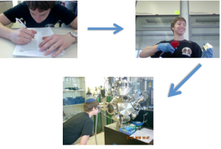
In each iteration, I ...
1. chose a glass substrate and deposition conditions (i.e. chamber temperature and pressure and laser pulse rate) based on literature and the results of my previous samples
2. rubbed the substrate clean with ethanol and water and dried it with an air gun
3. deposited a thin film of chromium oxide on the substrate using pulsed laser deposition (explained below)
BRAINSTORMING
My first task was to select a metal oxide with which to experiment. I read literature on previous experiments and sought the expertise of my professor.
I selected chromium oxide because of the paucity of existing research on this compound and my professor's advice.
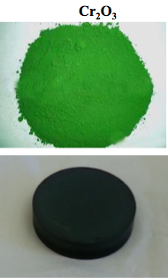
Top: Chromium oxide in its common light green form
Bottom: To design my solar cell samples, I used a dense disk of chromium oxide called a "target".
PULSED LASER DEPOSITION (PLD) MACHINE
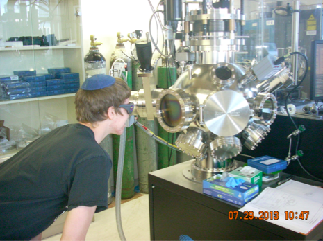
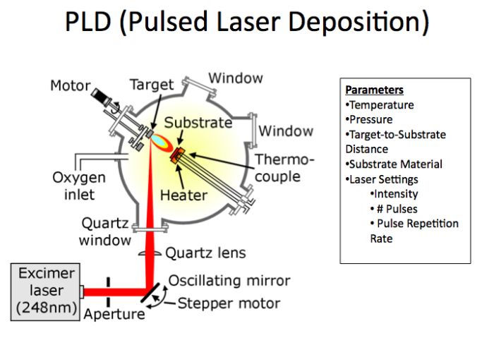
If you think the PLD machine is reminiscent of a scuba helmet from back in the day, that is no coincidence! Scuba helmets are designed to resist implosion due to higher external water pressure than internal atmospheric pressure. The PLD machine is designed to resist a similar pressure difference - external atmospheric pressure and internal vacuum pressure.
PLD OPERATION
Inside the PLD, a laser vaporizes particles off of the chromium oxide target into a plume of hot plasma. This hot plume then adheres to the glass substrate as a thin film.
DESIGN ITERATIONS
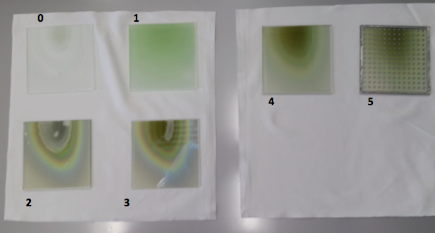
I designed three preliminary incomplete solar cell samples to compare the effectiveness of various fabrication conditions. In each iteration, I adjusted the substrate material and PLD conditions mentioned above.
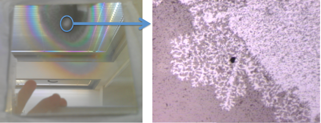
The thin film peeled off of the first three samples soon after I removed them from the PLD chamber.
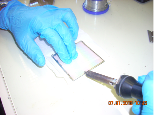
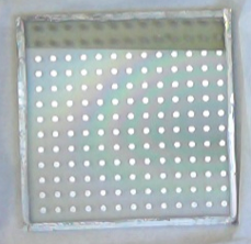
The 4th sample showed excellent adhesion, so I fabricated a complete solar cell on the same substrate material (fluorine-doped tin oxide) as sample 4 and with the same deposition conditions (400 degrees C, 0.55milliTorr). I completed this solar cell by soldering on tin siding and allowing a graduate student to sputter on silver back contacts (conductive circles). I then tested this 5th sample for electrical conductivity.
NOTE: Sample 0 was simply for practice operating the PLD machine.
Soldering on tin siding
HOW THIN FILM SOLAR CELLS WORK
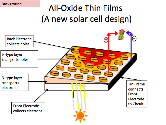
Sunlight generates exciton pairs, a P-N junction transports the holes and electrons to opposite sides of the cell. Circular silver back contacts and tin soldering conduct the holes and electrons away from the cell to complete a circuit that can power a lightbulb or... a rotating ice cream cone. The brown to yellow transition represents the thickness gradient of the deposition. This thickness gradient allowed me to test the properties of many solar cell designs of various thicknesses in just one sample.
TESTING
I observed all five samples' adhesion with an Olympus AX70 microscope.
I observed the 4th sample's crystal structure and its ability to absorb photons using x-ray diffraction and an optical scanner respectively.
I measured the 5th sample's electrical conductivity using a current-voltage scanner.
FINAL PRODUCT
My 5th sample, like most experimental solar cell designs, had an efficiency of less than 1% and will not be useful in solar panels.
On the other hand, my samples' settings and performance results will inform the lab group's selection of materials for future experiments. Every success and failure in solar cell experimentation is one step closer to a viable design.
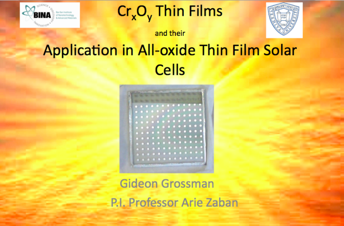
Complete solar cell sample. The rainbow arch emanating from the right hand side of the solar cell shows the thickness gradient of deposited chromium oxide. The reason for this thickness gradient and the reason why the cell has 13 x 13 = 169 silver back contacts, rather than one, was to allow me to test the properties of 169 designs in just one sample. The electrical conductivity at each of these dots was less than 1%.
gLike