
Please Note: The text accompanying this portfolio piece assumes some familiarity with electronics.

I'm a front-end developer; I love CSS and Adobe products, and hardware is largely outside my scope. However, I decided I wanted to try something new, and took an embedded systems class at my university. MusiCollab is my final project for this class.
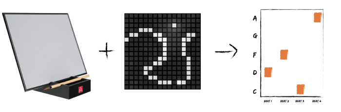
MusiCollab is the combination of two mediums: art and sound. Think of a canvas that lights up in response to touch. Then imagine that canvas is covering a continuously looping grid of musical notes, and the lights that appear correspond to the current tone being played. This is MusiCollab in a nutshell--the impermanence of a Buddha Board with the musical element of a tone matrix (tonematrix.audiotool.com)
Especially when we feel inexperienced in a medium, it’s easy to place the perceived barrier to entry so high that we’ll simply say “I’m not creative”, “I’m not musical”, or something of that ilk. However, taking this activity out of context (removing physical instruments from a musical setting, for example) can trick our brains into letting us try things because the perceived risk is much lower.
In the concept diagram (far right), each row is a different note in the pentatonic scale (a musical scale used in improvisation), and each column represents a beat. The twist, however, is that a tone only plays a couple of times before fading from the melody. The result is an unconventional instrument that creates a continuously changing soundscape. Currently, MusiCollab consists of one bar (4 beats) of music, with a full octave pentatonic scale (5 tones) to choose from for each beat.

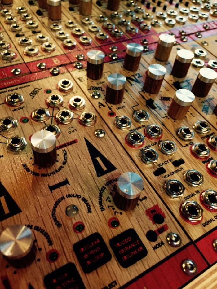
The first step was to get a feel for what's already on the market. To do this, we went to FoxTone Music in Minneapolis to look at their variety of pedals and boards. There was something beautiful about them--the layout of the buttons and switches, the graphics, the lights. We also realized the general aesthetic was pretty rough around the edges. There was lots of exposed soldering, and a lot of the smaller boards had a very circuit-board-esque vibe.


There were three main iterations of this project. The first phase used a Pololu A-Star 32U4 and pressure sensors. The idea was to use an array of square FSRs (force-sensitive resistors) to detect touch. Once the pressure sensor reach above a certain threshold, the sensor would be read as "on". By adjusting this threshold, this would also let us adjust the touch sensitivity, thus allowing the user to interact by gliding along the surface.
After some research however, this seemed less-than feasible. Generally, there are two ways to check the state of a sensor: interrupts and polling. Polling involves manually checking each sensor constant intervals, whereas interrupts allow the sensor to interrupt your code's execution to trigger another task. In simpler terms, polling is the "are we there yet?" approach to programming, and interrupts simply tell you when you've arrived.
Using analog sensors (that can have a range of values--as opposed to simple on/off switches like push buttons) made using interrupts nearly impossible. Analog interrupts require an analog comparator (i.e. a reference value), and the Pololu only allowed this on 1 pin--we needed 20.
Polling was similarly thwarted. Reading a pressure sensor is relatively slow computation-wise, so polling each of our 20 FSRs would have taken enough time to affect the responsiveness of the system--in the worst case, a touch wouldn't get registered because the length of touch was shorter than the amount of time until that sensor was checked again.
We decided to pivot. After some reading online, I found a really cool circuit design called the Darlington Configuration. It's a touch-sensitive switch developed at Bell Labs back in the day, and uses only 2 transistors and some wire. We also switched over to the Arduino Mega, which has 24 interrupts (as opposed to the Pololu's 12).
I set to work soldering, color-coding the wires for readability. Since I didn't have much experience with soldering, it was definitely slow going. After a late night of solder fumes, broken code, and intravenous caffeine, I ended up with five completed circuits.
Unfortunately, I'm not much of a solderer. The 5 Darlingtons I configured onto the protoboard worked intermittently at best, despite testing them as I was working. Discouraged, I learned how to use a multimeter to check all of my connections, and was still unable to diagnose the problem.
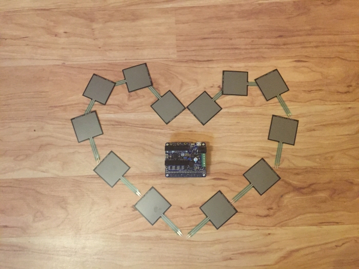
That's when my partner found a really cool arduino library for sensing capacitive touch. Compared to the Darlington Configuration, the code and the circuitry were both much simpler, so it seemed like a good option to at least try before sinking endless time into debugging the current version. It ended up working like a charm!
Below is another quick proof-of-concept video using a 10 MOhm resistor and aluminum foil. Completing the circuit causes an LED to light up. This was programmed using polling on an Arduion Mega 2560.

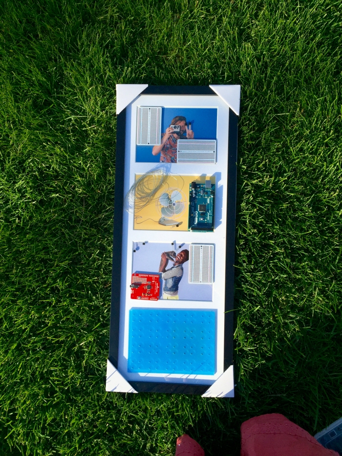
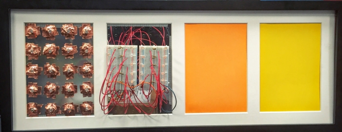
We decided to go with a photo frame aesthetic. In a perfect world, each of the four photo slots would represent 1 bar (4 beats) of music, creating a loop of 16 beats total. This is a really common unit of western music, so the loop would sound natural to our ears.
Due to time constraints, however, we decided to just make one panel. We collected our electronics and began assembling.
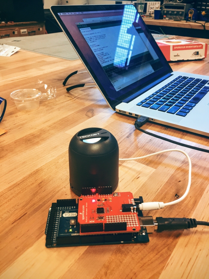
To make sound, we ended up using an MIDI shield and a speaker.This shield is designed to work with smaller Arduinos (like the Uno), but worked just fine with the larger, Mega board.
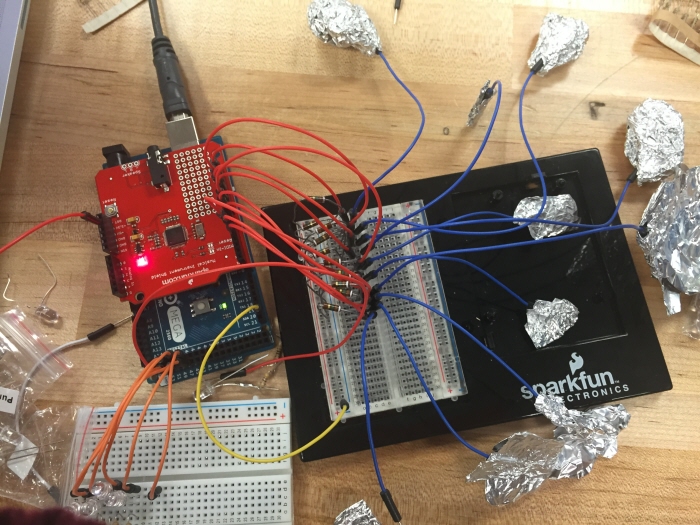
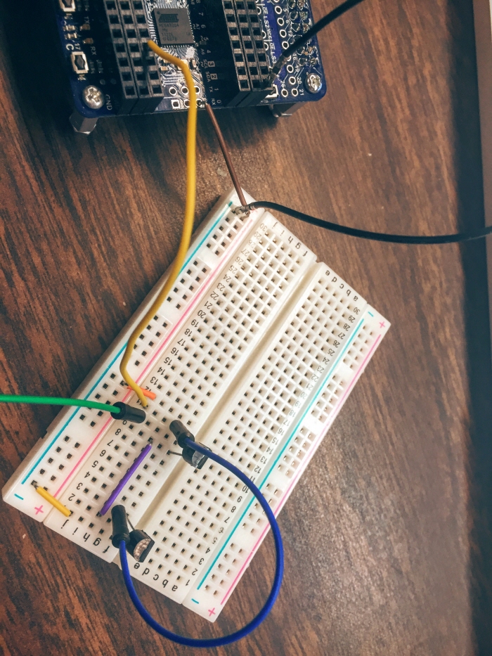
To avoid unwanted surprises this time around, we prototyped the circuit with 10 sensors before making it permanent. Each of these sensors plays a different tone when touched.
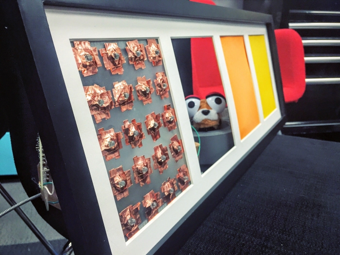
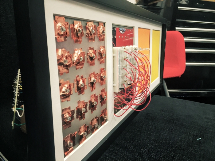
Assembling the photo frame took hours, but the end result looked surprisingly clean. The final sensors are using copper tape, which is conductive, adhesive, and much easier to work with than aluminum foil. After testing that the tone functionality was working (there's an external speaker hidden behind the frame), we wanted to add in LEDs to light up when each corresponding note is played. While a fully-finished prototype would have these LEDs in the same panel as the sensors, we decided to breadboard them in the next frame as a proof-of-concept.

Right now, MusiCollab is functional--you can touch the capacitance sensors and, more often than not, a note plays and the corresponding LED lights up as feedback. However, there's still a lot that stands to improve.
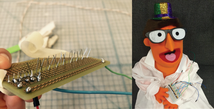
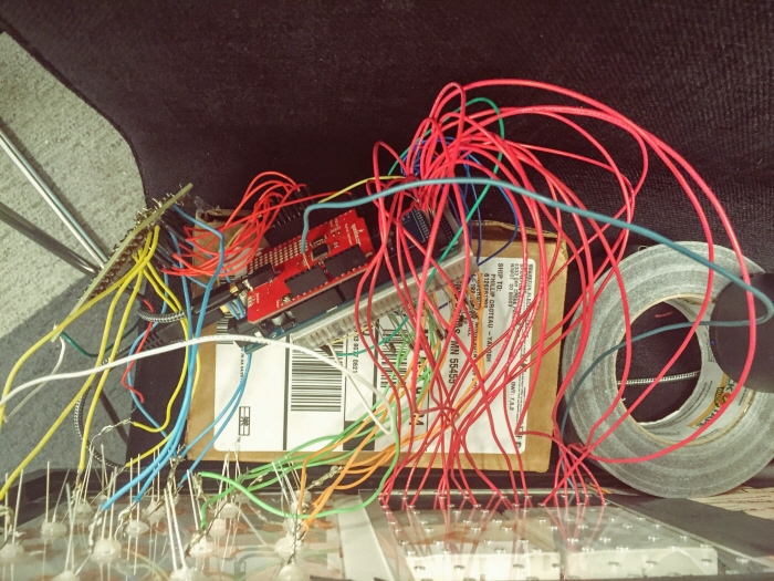
First off, the LEDs were originally supposed to be in the same frame, but the wiring from the sensors proved too difficult to work around. As such, there are 20 un-wired LEDs on the sensor panel that should be used in place of the LEDs on the second panel. Despite good intentions, my novice-level electrical engineering skills ran the wiring amuck in record time:
Finally, the ideal scale for this project is 4 bars (16 beats) of music, so this prototype is only a quarter of the way there. To achieve this, however, my approach would need to be largely re-imagined.
For a larger implementation, I would want to keep the number of wires to a minimum, probably by using a large protoboard and soldering all my circuitry directly to it. This would also make for a much more stable, durable product.
Programming-wise, I'm really happy with both the Arduino language and the CapSense library used for the capacitance sensors. I think the biggest improvement would be to generalize MIDI my code. I currently have four functions: playBeatOne(), playBeatTwo(), playBeatThree(), and playBeatFour(). They all do exactly the same thing, but are hardcoded to modify the correct pins, so my next step would be to abstract out a playBeat() function that works in all cases (probably by passing pointers). This is not only easier to read, but also much easier to maintain.

This project was an exercise in persistence and pivoting.
I definitely improved my soldering chops. I soldered pressure sensors, transistors, resistors, LEDs, and wires galore. Even when the final circuits weren't successful, the repetition was helpful for more consistent solders and less burned fingers.
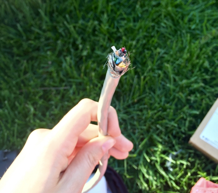
I also got a much more low-level understanding of some basic electronics hardware. I learned how to build a pushbutton circuit out of wire, finally understood how a simple LED circuit works, and spent a lot of time understanding the inner-workings of transistors. I even disassembled a length of cable to use the smaller wires inside (an attempt to be thrifty), and was fascinated by the anatomy of it--however, it also taught me never to take for granted the luxury of solid-core wire.
Finally, doing this project made me realize just how much I've learned in this class. When I was having problems with my board, my first instinct was to reference the data sheet, and even understood what it said! I also found myself having an intuition for whether a problem was hardware or software related, as well as coming up with quick ways to isolate and test functionality.
Conceptually, I was able to gain experience with scheduling tasks in a system. Since we ended up going with polling instead of interrupts, I had to find elegant ways to continuously poll my 20 sensors without disrupting the music being played.
Considering that my electronics experience prior to this class was limited at best, I'm really happy with how this project turned out. I worked with multiple boards, circuits, and coding languages, and came to feel comfortable in each one. Even the smaller things (like how a pushbutton works) gave me a much more thorough understanding of real-time and embedded systems.
gLike